Fueling & Injection (Open & Closed Loop)
Concepts
Air-Fuel Ratio/Lambda
Combustion and Air-Fuel Ratio
Gasoline engines operate on the principle of fuel combustion. By approximating the mass (not to be confused with volume) of air entering a cylinder from the intake manifold prior to fuel injection, a calculation can be made to determine the necessary mass of fuel based on the desired target air-fuel ratio, or the ratio of units air mass to units fuel mass, for the intended combustion.
Depending on the conditions of the engine, such as load (grams of air mass per crank revolution) and engine rotation speed (RPM), varying air-fuel ratios will be required. A carefully selected air-fuel ratio for the engine's operating conditions will include the following benefits:
- The resistance to, or avoidance of detonation (or "knock") occurring inside a cylinder during or prior to intended, controlled combustion (which starts with the spark).
- Ensuring complete combustion, where the injected fuel is ideally mixed and combusted, which among several things, results in greater efficiency and more effective extraction of possible force on the cylinder's piston.
- Avoidance of excessive combustion temperatures that can cause damage to any metal surfaces inside the cylinder (melting) or pressures that are outside of the design limitations (relating back to knock).
How Air-Fuel Ratio is Realized
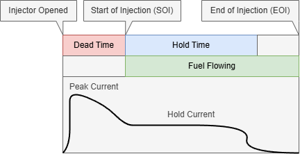
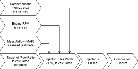
Using the fuel mass derived from the air-fuel ratio and other factors, a calculation can be made to approximate the necessary duration of duty time ("pulse width") that the to-be-fired cylinder's corresponding injector should be electrically signaled to open, permitting fuel to spray into the cylinder. The longer the injector stays open, the more fuel mass is injected directly into the cylinder, and the shorter the time the injector is open, the less fuel is injected. This injection time is called the injector pulse width, or "IPW" for short, where width refers to the duration of time the injector should remain open, typically represented in milliseconds (ms). This is not necessarily the same as the injector hold time.

Please note that, in the above graphic, time (X axis) is not to scale.
Other physical effects are factored during this calculation of pulse width, such as the fuel's delivery pressure behind the injector (fuel rail pressure), intake air density, coolant temperature, and so on, in order to estimate the precise amount of fuel being delivered as accurately as possible. Any modifications that affect this calculation are considered compensations (for physical effects) or trims (for controlling a target air-fuel ratio).
Open vs. Closed Loop Fueling (Abstract)
Open Loop and Positives/Negatives
Although it is possible to estimate the ideal injector pulse width (IPW) to within a close margin, error accumulating from all sensor readings (of which there are many involved), calibration imprecision, and even rounding issues within the ECU's binary logic will effectively cause the calculated pulse width to the injectors to never be perfect. This means that, instead of injecting an ideal mass of fuel, the ECU will always be injecting some amount more (richer) or less (leaner) than the intended mass as it relates to the physical target air-fuel ratio by some unpredictable margin.
The process of injecting fuel into a cylinder without any sensor feedback on the resulting air-fuel ratio (in this case, the setpoint) is called Open Loop.

Open Loop presents a problem when tight control over the real, physical air-fuel ratio is necessary: in a modern vehicle with lower margins of safety and greater incentive to optimize combustion efficiency, where the limitations to fueling are approached more aggressively, these errors can have a more significant impact on causing engine knock. Additionally, with an OEM assumption of the fuel's energy density, which is typically only ever assumed to be that of gasoline unless modified (i.e. flex fuel), combustion will be negatively impacted when fuels with unanticipated energy densities are used or mixed (i.e. E85). Due to these restrictions, often a tuner will enrich (add fuel) in the Open Loop air-fuel ratio target map(s) in order to add a margin of safety to combustion, but this still does not cover the bases for all scenarios where Open Loop has challenges.
On the other hand, Open Loop is fast. Where Closed Loop control requires a fixed amount of time to sense the combustion products and derive an approximate result of air-fuel ratio, Open Loop quickly commands an estimated value. Depending on the strategy taken by the tuner, Open Loop can be an effective way to control effective combustion in an engine in scenarios where delayed feedback (trim) to air-fuel ratio is not an option. Additionally, Open Loop is ideal in scenarios such as malfunctioning air-fuel sensors for Closed Loop, or simply not having them physically present/available. This can sometimes be the case on extremely high flow/horsepower engines, older vehicles without Closed Loop-specific feedback sensors, or even scenarios where the fuel type being used is trusted to be highly consistent.
Closed Loop and Positives/Negatives
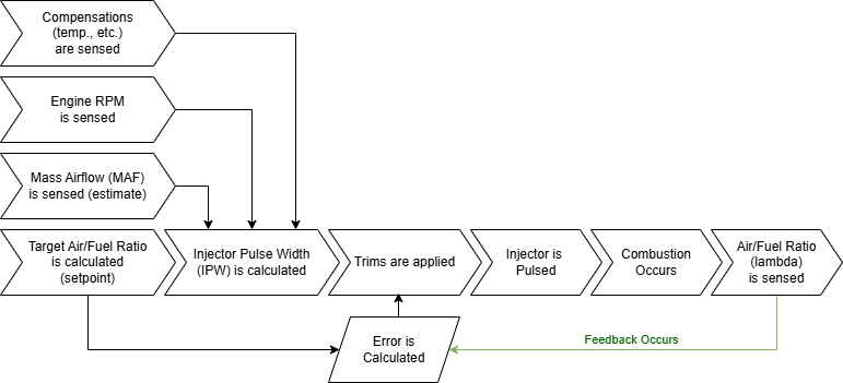
Due to the challenges presented by Open Loop control, most modern ECUs control the injector pulse width based on the feedback signaled from physical sensors in the exhaust path. This feedback, in the form of the physical air-fuel ratio (often expressed as lambda), is used to adjust (trim) the injector pulse width to account for the error observed between the sensed air-fuel ratio and the target air-fuel ratio (also known as the setpoint). This process of relying on feedback to adjust the commanded value is referred to as Closed Loop control.

Closed Loop control solves several issues with Open Loop control:
- Open Loop is not sensitive to any changes in a fuel's energy density (i.e. blending ethanol), while Closed Loop control can adjust for these changes, although only up to defined limits.
- Open Loop is not sensitive to long-term changes in combustion, such as those created by carbon build-up on intake values disrupting airflow, while Closed Loop control can learn these deltas over time.
- Open Loop is not sensitive to errors in the air-fuel calculation caused by an improper calibration of the Mass Airflow (MAF) sensor, for example when replacing an intake with an aftermarket intake, while Closed Loop control can learn from these discrepancies. This is a critically important advantage for calibrating aftermarket intakes.
Closed Loop control has drawbacks, however. When in Closed Loop mode, an ECU will make adjustments based on the downstream products of combustion after it has happened. Along with time-consuming signal processing such as smoothing, the sensed lambda value will be electrically delayed by some deterministic amount of time after the commanded pulse width value had been electrically commanded and combustion had physically occurred. Due to this discrepancy, errors in the approximated pulse width are never perfectly corrected in advance, but instead are corrected continuously with calculated trims. Also, if the feedback delay is out of a preset tolerable value (limit), then Closed Loop control cannot take place.
Closed Loop relies on sensors to determine error, which unfortunately means that if sensors downstream of combustion, relied upon for reporting accurate estimations of air-fuel ratios, are not functioning properly, the corresponding calculated error (and therefore the trims) will be inaccurate as well.
Key Hardware Sensors
Mass Airflow (MAF) Sensor
In order for the ECU to calculate and balance an injector pulse width (IPW) that harmonizes to the air-fuel ratio (lambda) value requested by the tune, an accurate estimation of the mass of air entering the cylinder (also referred to as engine load) must be calculated. To calculate this value, expressed in grams of air per crank revolution of the engine, first a mass airflow value (in grams per second) that represents the mass of air flowing through the engine's intake tract (or intake manifold) must be approximated.
On a Subaru DI engine from factory, this is done using a Mass Airflow (MAF) Sensor. Typically, this sensor is positioned inside the intake piping immediately after the air filter, right at the entry-point of air for the vehicle's intake system. Then, a wire positioned within and exposed to the intake air stream is heated. The electrical characteristics of the wire as it responds to the flowing air mass affecting its temperature is measured, and the resulting value (voltage or otherwise) is mapped to a resulting mass airflow value by the tune/calibration. This is the standard, Subaru factory strategy of calculating engine load.
On some engines, and in tunes using Speed Density, this can be approximated indirectly using the Manifold Absolute Pressure (MAP) Sensor. In this scenario, the barometric pressure (absolute) of air in the intake manifold (density) is measured along with the temperature. Also factoring the engine speed (RPM), other compensations, and a map of the engine's volumetric efficiency, a mass of air entering cylinders can be closely approximated. This is not the standard, factory strategy of calculating engine load for Subaru ECUs. However, this method does offer some advantages over a mass airflow sensor.
Narrowband O2 Sensor
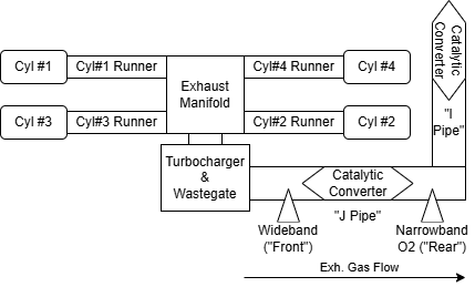
An oxygen sensor (or O2 sensor) is a physical sensor that is incorporated into the exhaust piping of the engine, with one being placed immediately after the primary catalytic converter in the Subaru DI factory arrangement.
Oxygen sensors, by interacting with exhaust gases, provide a value relative to the stoichiometric ratio that assists the ECU in approximating if the air-fuel ratio was richer (more fuel) or leaner (less fuel) than the ideal combustion ratio. It is important to underscore that these sensors are in essence providing an approximation of the relative direction of error of lambda value 1.0 of combustion. For example, a lambda value of 1.0 would be equal to an air-fuel ratio of about 14.7:1 for gasoline, and about 9.76:1 for E85. However, narrowband sensors cannot provide an accurate value for the combustion air-fuel ratio, only its relation to the stoichiometric ratio: if combustion was above or below that ratio, and a loose approximation of how significant the error is.
The role of the narrowband O2 sensor in the Subaru DI arrangement, being so limited in its capabilities, is not to determine the air-fuel ratio of combustion across a wide range of possible values. Instead, it is primarily used for managing the catalyst efficiency through trims and monitoring its effectiveness when the engine is commanding an air-fuel ratio close to a stoichiometric target.
Wideband Lambda Sensor (Closed Loop)
A wideband sensor is a physical sensor that is incorporated into the exhaust piping of the engine, with one being placed immediately before the primary catalytic converter in the Subaru DI factory arrangement.
Wideband sensors, by interacting with exhaust gases, provide to the ECU a close approximation of the air-fuel ratio (lambda) condition that was present in the cylinder prior to combustion. This is a critically important sensor for Closed Loop control, as it provides the feedback value necessary to approximate the error between the commanded air-fuel target ratio and the physical combustion's indicated air-fuel ratio. The wideband sensor is able to sense this ratio as the exhaust gasses pass over it, flowing out of the engine through the exhaust piping where the wideband sensor is located after being collected by the exhaust manifold.
Using the wideband sensor in Closed Loop mode, the ECU is able to calculate an overall air-fuel ratio (lambda) error and generally speaking modulates (trims) the injector pulse width accordingly to compensate for any inaccuracies (too rich or too lean) in its pulse width calculations.
Subaru DI

Correction (Short-Term) Trims
A/F Correction #1
This is the short-term correction of the injector pulse width, sourced directly from the wideband lambda sensor. To produce this trim, the ECU first determines the error (delta) for the sensed air-fuel ratio (lambda) as it relates to the commanded air-fuel ratio. With this error, an excitation value is applied corresponding to the engine speed and load, effectively controlling the trim's activation based on the engine's operating condition.
This trim is only active in Closed Loop mode.
A/F Correction #3
This is the short-term correction of the air-fuel ratio (not to be confused with the injector pulse width), sourced directly from the narrowband O2 sensor. To produce this trim, the ECU determines a rough estimation of error from the narrowband O2 sensor.
This trim is only active in certain conditions, especially those that relate to the operation of the engine in an idle state, where the commanded air-fuel ratio is close to the stoichiometric ratio (or lambda 1.0).
Learning (Long-Term) Trims
A/F Learning #1
This is the long-term correction of the injector pulse width, sourced analytically from the wideband O2 sensor over time.
A/F Learning #3
This is the long-term correction of the air-fuel ratio (not to be confused with the injector pulse width), sourced analytically from the narrowband O2 sensor over time.
