# Subaru FA20/FA24 Direct Injection (DI)
Documentation and tuning resources for Subaru FA20/FA24 direct injected engines
# Ignition Timing & Knock Control
### Concepts
#### Ignition
For more information on how fuel is delivered, see our documentation page on [Fueling & Injection](https://docs.motorsportsresearch.org/books/tuning/page/fueling-injection-open-closed-loop)
**Ignition, Flame, and Degrees BTDC**
Gasoline engines operate on the principle of fuel [combustion](https://en.wikipedia.org/wiki/Combustion). Typically in a [direct injection system](https://en.wikipedia.org/wiki/Fuel_injection#Direct_injection_systems), first, fuel is [directly injected](https://en.wikipedia.org/wiki/Gasoline_direct_injection) into a cylinder some time before the spark is ignited. Additionally, it is compressed during the [compression stroke](https://en.wikipedia.org/wiki/Stroke_(engine)) as the piston travels upwards towards top [dead center](https://en.wikipedia.org/wiki/Dead_centre_(engineering)) (TDC). Relative to the top dead center position, and with its timing precisely controlled by the tuner's map, the [spark plug](https://en.wikipedia.org/wiki/Spark_plug) is electrically ignited by a signal sent from the ECU to start the process of combustion.
Once combustion is started ideally with the spark plug, a flame front propagates evenly throughout the cylinder at a [specific speed](https://en.wikipedia.org/wiki/Flame_speed) relative to factors such as the fuel sprayed and the [air-fuel ratio](https://en.wikipedia.org/wiki/Air%E2%80%93fuel_ratio). Due to the flame's propagation speed and a goal of complete combustion, the ignition of the spark plug should be timed early enough in the piston's movement that the flame can fully propagate within the available time window up to the end of the exhaust stroke, helping to ensure that the air-fuel mixture is entirely combusted before the gasses are exhausted. Additionally, the timing of the flame propagation can be precisely controlled by the spark's timing to exact an idealized amount of force on the piston as it travels downwards during the power stroke, encouraging efficient energy extraction from the fuel-air mixture.
To control this ignition timing, the [ECU](https://en.wikipedia.org/wiki/Engine_control_unit) has a series of maps that define when the ignition spark should take place relative to the top dead center position of the piston as it ends the compression stroke. Typically, and in the Subaru DI logic, this timing is measured in degrees before the top dead center position, or BTDC. In this case, the degrees in the measurement relates to the degrees of crankshaft rotation of the engine, with a 4 stroke engine (such as the FA24) taking two full revolutions (or 720 degrees) for all 4 strokes to take place. Here is a reference of BTDC values and the timing they are associated with relative to cylinder events:
Extreme values such as 90.00°, and 180.00°, negative or otherwise, are only provided as an example reference to cylinder events; these values are entirely unrealistic for engine operation, and **should not be used in real-world tuning**.
| **Degrees Before Top Dead Center (BTDC)** | **Relative to TDC** | **Event** |
| `180.00°` | Before | End of intake stroke, beginning of compression stroke. |
| `90.00°` | Before | Half-way through compression stroke, piston travels upwards towards the valves. |
| `0.00°` | TDC | Top dead center, power stroke begins. |
| `-90.00°` | After | Half-way through power stroke, piston travels downwards towards the crank-shaft. |
| `-180.00°` | After | End of power stroke, beginning of exhaust stroke. |
#### Detonation (or "Knock")
**Detonation and Pre-detonation**
In the ideal scenario, the ignition of the air-fuel mixture in a cylinder will result in a single, evenly propagating flame front that expands outward from the spark plug at a predictable and controlled rate of expansion. This controlled expansion of the flame front results in a linear, even pressure across the cylinder walls and the piston's surface. However, it is unfortunately possible for the air-fuel mixture to spontaneously ignite in various conditions, causing one or more flame fronts to propagate throughout the cylinder's volume in an uncontrolled manner.
This spontaneous ignition of the air-fuel mixture is referred to as **[detonation](https://en.wikipedia.org/wiki/Engine_knocking)** due to the (sometimes audible) sound that is produced by multiple flame fronts colliding with each-other and creating extremely high pressure spikes inside the cylinder. Due to this sound, detonation is sometimes referred to as *knock;* not to be confused with *rod knock*, which is an entirely different phenomenon. These collisions can directly cause damage to the cylinder walls, valves, head surface, and piston surface.
**Pre-detonation** is similar to detonation, but occurs *before* the spark ignites the air-fuel mixture, as opposed to detonation which occurs at some point *after* the spark ignites the air-fuel mixture.
In either case, the unpredictable pressures generated by any form of detonation can exact chaotic forces on the piston surface, suddenly forcing its connecting rod into the crankshaft, possibly damaging the [rod bearing](https://en.wikipedia.org/wiki/Plain_bearing). This is especially true for pre-detonation, where the spontaneous ignition can occur as the piston is completing its upwards travel to complete the compression stroke, violently interrupting the piston's only available direction of travel in possibly its most *critically* pressurized moment.
Detonation and pre-detonation can be caused by several factors, often compounding together simultaneously:
1. Faulty spark plugs or fuel injectors.
2. An air-fuel mixture that is too lean or too rich for proper combustion with cylinder conditions.
3. Low [fuel octane](https://en.wikipedia.org/wiki/Octane_rating), the measurable capability of a fuel to resist detonation. Fuels such as 93 or E85 have a higher octane rating than perhaps 87 or 91, but it is possible for fuel to lose octane after sitting for a long period of time. Fuel octane can be affected by any contaminants such as oil or coolant mixing with the air and fuel in a cylinder.
4. An ignition timing value that is too advanced (earlier in time).
5. A [compression ratio](https://en.wikipedia.org/wiki/Compression_ratio) incompatible with cylinder conditions and the commanded ignition timing. Compression ratios can be increased by carbon deposits (buildup) inside a cylinder.
6. Excessive temperatures inside the cylinder, including air temperature and hot spots within the cylinder surfaces. Carbon deposits can also be sources of these hot spots.
### Subaru Knock Control
#### Introduction
**Mitigation**
As detonation and pre-detonation can be dangerous events, entirely eliminating all forms of detonation (or "knock") is an extremely important goal of any gasoline ignition strategy. By reducing (also referred to as retarding or pulling) the base ignition timing *later* in the engine cycle or by modifying the air-fuel ratio, it is possible for an ECU to significantly mitigate detonation events. While pre-detonation can be mitigated this way as well, it is likely that additional factors are involved if it is occurring.
Unfortunately, delaying the ignition timing implies that torque would likely be lost due to the decreased mechanical advantage imparted by the piston on the crankshaft from the flame front's delayed propagation. However, this is a valuable trade-off, as an engine won't be making *any* torque (or, at best, significantly less) if severe detonation event(s) occur and cause damage to cylinders or other engine components.
**Why Pull Timing?**
It is important to note that if we are reducing (pulling back) ignition timing, we are effectively delaying (or retarding) the spark event's occurrence in time relative to the engine's cycle. This has effects that help mitigate detonation, with one primary advantage being that we are allowing for more time for [entropy](https://en.wikipedia.org/wiki/Entropy) to do its job and to enabling the air and fuel to mix within the volume of the cylinder.
Additionally, the environment within the cylinder becomes less favorable for detonation as the piston moves past its top dead center (0 degrees BTDC) and travels downward in the power stroke. This downward motion has the important effect of increasing the cylinder [volume](https://en.wikipedia.org/wiki/Volume), which correspondingly decreases the air-fuel mixture's [density](https://en.wikipedia.org/wiki/Density) as the valves remain during the power stroke. This reduction of density reduces the cylinder's pressure and temperature, both highly advantageous effects to mitigate detonation.
#### Sensors
**Knock Sensors**
On the Subaru FA platform, two [piezoelectric sensors](https://en.wikipedia.org/wiki/Piezoelectric_sensor) called [knock sensors](https://en.wikipedia.org/wiki/Engine_knocking#Knock_detection) are bolted directly onto the factory [short block](https://en.wikipedia.org/wiki/Automobile_engine_replacement#Short_block). With both positioned in the rear of the [crankcase](https://en.wikipedia.org/wiki/Crankcase), nearest the [bell housing](https://en.wikipedia.org/wiki/Bell_housing), each sensor is allocated to a [cylinder bank](https://en.wikipedia.org/wiki/Engine_configuration#Piston_engines). As Subaru engines utilize the [boxer engine](https://en.wikipedia.org/wiki/Flat-four_engine) layout, this means that the knock sensors are assigned to each case half, with the left sensor corresponding to cylinders #3 and #1, and the right sensor corresponding to cylinders #4 and #2.
Acting as microphones, the knock sensors perceive vibrations propagating throughout the block in a similar manner a traditional microphone would record pressure waves in open air. By filtering and analyzing the signal received and restricting the recording time window to the firing cylinder's ignition time window, the ECU can take advantage of these sensors to approximate an extremely important feedback on the occurrence detonation, which itself is a noisy (and sometimes even audible) event.
#### Mitigation Stategies
**Introduction**
The Subaru factory logic, including that of the DI models such as the FA20 and FA24, utilize three distinct methods to manage detonation (or "knock") in its ignition timing system. Each relies on the principle of reducing (or pulling) ignition timing. All three systems are permanently active and each can affect the ignition timing directly at any point in time if necessary.
**Feedback Knock (FBK)**
Feedback Knock is the component of the OEM strategy responsible for the **short-term** component of detonation mitigation. The ECU leverages the knock sensors to continuously analyze and perceive suspected detonation events in the form of recorded audio events in real-time. Once the intensity of an event exceeds a threshold defined in the table group **Knock Control - Threshold**, a binary signal is generated that indicates the presence of ongoing detonation.
The **Feedback Knock** value will be decremented according to a magnitude corresponding to a calibration value. As the detonation event is mitigated or is resolved, the Feedback Knock value will return to a value of 0.0. Greater values seen from the Feedback Knock parameter are indicative of a more significant detonation event. Steadily or sharply increasing values are indicative of an event requiring more negative timing to mitigate, while small (-1.41, etc.) values that do not increase are indicative of possible noise or a much shorter event.
The value of the Feedback Knock parameter is directly used as a **subtraction** from the **final ignition timing**. It is always active. In this way, the Feedback Knock is effectively able to respond quickly to transient detonation events for future cylinder firing events, but has the disadvantage of not being capable of preventing the first events that trigger it. This is, of course, due to the fact that it relies on these events occurring to react in the first place, even if it may be quick to mitigate them.
When troubleshooting the Feedback Knock parameter demonstrating timing subtractions for a possible tune modification, it is important to classify the problem by analyzing the overall event and the engine conditions during it. For example, was the negative value seen during deceleration, light load, heavy load (a pull), or transient (quickly changing) conditions? What fuel was used, and what was its octane rating? Were new parts or mounts installed on the vehicle that may have increased vibrations? What parameters were recently modified in the tune?
If it is difficult to reproduce the subtraction in an identical environment and condition, it likely would have been noise, especially for smaller feedback values. If it is readily repeatable, even semi-consistently, there likely is either an real issue with true detonation or the sensors are consistently recognizing noise from vibrations present only during certain conditions.
**Fine Knock Learn (FKL)**
To account for the shortcomings of the Feedback Knock strategy, Fine Knock Learn provides the **long-term** component of detonation mitigation, as a subtraction in degrees before top dead center (BTDC). As detonation events are observed, the ECU records these events and persists them in a long-term storage system called the [EEPROM](https://en.wikipedia.org/wiki/EEPROM). Internally, the ECU records these ignition timing subtractions in a small table based on the engine speed (RPM) and the calculated load (g/rev) at the time of the events.
Fine Knock Learn can return to its normal state of 0.0 degrees subtracted from the ignition timing, but only when detonation events have not been seen in the affected operating condition's cells.
By looking up this table before ignition occurs, the Fine Knock Learn parameter can express an engine condition-specific value that assists in mitigating detonation before it can occur, unlike Feedback Knock. However, Fine Knock Learn cannot react to transient events, so these two systems operate in tandem to provide continuous short and long-term coverage for both transient and recurrent detonation activity, respectively.
Troubleshooting the Fine Knock Learn parameter can be slightly easier than troubleshooting the Feedback Knock parameter, as the important question of replicability has likely already been answered - values present in this learning table are normally recurrent. First, identify which cell(s) in the table the ignition subtraction(s) have been recorded to. Using this engine condition, run through the same troubleshooting steps as the Feedback Knock parameter, but instead with the assumption that these events have likely been recurrent.
**Dynamic Advance Multiplier (DAM)**
A third, broad-stroke strategy used by the Subaru ignition timing control system is the **Dynamic Advance Multiplier**. Unlike the Feedback Knock and Fine Knock Learn parameters, the Dynamic Advance Multiplier (or "DAM") parameter is a number ranging from 0.0 to 1.0, and acts as a scaling (activation) value against the Ignition **Dynamic Advance** tables.
To determine a base ignition timing value, first the base ignition timing tables are calculated for the current engine speed (RPM) and load (g/rev). Then, the Dynamic Advance tables are processed. But, before adding this additional timing advance on top of the base timing, it is first multiplied by the Dynamic Advance Multiplier value. In this way, the Dynamic Advance Multiplier acts as an activation for additional timing in the map.
The Dynamic Advance Multiplier can be decreased (reducing the base timing advance) if detonation events are seen, similar to how the Feedback Knock system works, but instead of directly controlling ignition timing, these events (if significant enough) can reduce a multiplier. Unlike Feedback Knock, however, increases to the Dynamic Advance Multiplier behave more similarly to Fine Knock Learn, where the DAM value will increase as detonation events are *not* seen during critical operation such as heavy acceleration (a pull).
# Fueling & Injection (Open & Closed Loop)
### Concepts
#### Air-Fuel Ratio/Lambda
**Combustion and Air-Fuel Ratio**
Gasoline engines operate on the principle of fuel [combustion](https://en.wikipedia.org/wiki/Combustion). By approximating the [mass](https://en.wikipedia.org/wiki/Mass) (not to be confused with volume) of air entering a cylinder from the [intake manifold](https://en.wikipedia.org/wiki/Inlet_manifold) prior to [fuel injection](https://en.wikipedia.org/wiki/Fuel_injection), a calculation can be made to determine the necessary mass of fuel based on the desired **target [air-fuel ratio](https://en.wikipedia.org/wiki/Air%E2%80%93fuel_ratio)**, or the *ratio of units air mass to units fuel mass*, for the intended combustion.
Depending on the conditions of the engine, such as load (grams of air mass per crank revolution) and engine rotation speed (RPM), varying air-fuel ratios will be required. A carefully selected air-fuel ratio for the engine's operating conditions will include the following benefits:
- The resistance to, or avoidance of [detonation](https://en.wikipedia.org/wiki/Engine_knocking) (or "knock") occurring inside a cylinder during or prior to intended, controlled combustion (which starts with the [spark](https://en.wikipedia.org/wiki/Spark-ignition_engine)).
- Ensuring complete combustion, where the injected fuel is ideally mixed and combusted, which among several things, results in greater efficiency and more effective extraction of possible force on the cylinder's piston.
- Avoidance of excessive combustion temperatures that can cause damage to any metal surfaces inside the cylinder (melting) or pressures that are outside of the design limitations (relating back to knock).
**How Air-Fuel Ratio is Realized**
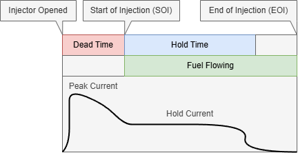
Using the fuel mass derived from the air-fuel ratio and other factors, a calculation can be made to approximate the necessary duration of duty time ("pulse width") that the to-be-fired cylinder's corresponding injector should be electrically signaled to open, permitting fuel to spray into the cylinder. The longer the injector stays open, the more fuel mass is injected directly into the cylinder, and the shorter the time the injector is open, the less fuel is injected. This injection time is called the injector pulse width, or "IPW" for short, where *width* refers to the duration of time the injector should remain open, typically represented in milliseconds (ms). This is not necessarily the same as the injector hold time.
*Please note that, in the above graphic, time (X axis) is not to scale.*
Other physical effects are factored during this calculation of pulse width, such as the fuel's delivery pressure behind the injector (fuel rail pressure), intake air density, coolant temperature, and so on, in order to estimate the precise amount of fuel being delivered as accurately as possible. Any modifications that affect this calculation are considered **compensations** (for physical effects) or **trims** (for controlling a target air-fuel ratio).
#### Open vs. Closed Loop Fueling (Abstract)
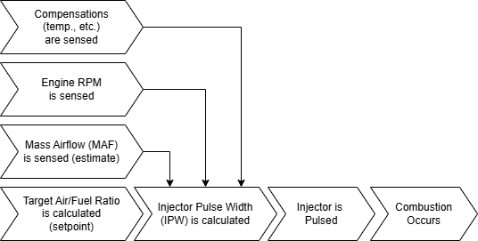
**Open Loop and Positives/Negatives**
Although it is possible to estimate the ideal injector pulse width (IPW) to within a close margin, error accumulating from all sensor readings (of which there are many involved), calibration imprecision, and even rounding issues within the ECU's binary logic will effectively cause the calculated pulse width to the injectors to never be perfect. This means that, instead of injecting an ideal mass of fuel, the ECU will always be injecting some amount more (richer) or less (leaner) than the intended mass as it relates to the physical target air-fuel ratio by some unpredictable margin.
The process of injecting fuel into a cylinder without any sensor feedback on the resulting air-fuel ratio (in this case, the setpoint) is called [**Open Loop**](https://en.wikipedia.org/wiki/Open-loop_controller).
Open Loop presents a problem when tight control over the real, physical air-fuel ratio is necessary: in a modern vehicle with lower margins of safety and greater incentive to optimize combustion efficiency, where the limitations to fueling are approached more aggressively, these errors can have a more significant impact on causing engine knock. Additionally, with an OEM assumption of the fuel's [energy density](https://en.wikipedia.org/wiki/Energy_density), which is typically only ever assumed to be that of gasoline unless modified (i.e. flex fuel), combustion will be negatively impacted when fuels with unanticipated energy densities are used or mixed (i.e. E85). Due to these restrictions, often a tuner will enrich (add fuel) in the Open Loop air-fuel ratio target map(s) in order to add a margin of safety to combustion, but this still does not cover the bases for all scenarios where Open Loop has challenges.
On the other hand, Open Loop is fast. Where Closed Loop control requires a fixed amount of time to sense the combustion products and derive an approximate result of air-fuel ratio, Open Loop quickly commands an estimated value. Depending on the strategy taken by the tuner, Open Loop can be an effective way to control effective combustion in an engine in scenarios where delayed feedback (trim) to air-fuel ratio is not an option. Additionally, Open Loop is ideal in scenarios such as malfunctioning air-fuel sensors for Closed Loop, or simply not having them physically present/available. This can sometimes be the case on extremely high flow/horsepower engines, older vehicles without Closed Loop-specific feedback sensors, or even scenarios where the fuel type being used is trusted to be highly consistent.
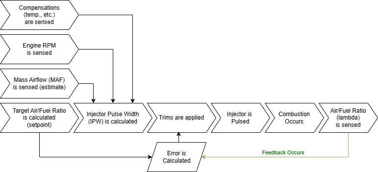
**Closed Loop and Positives/Negatives**
Due to the challenges presented by Open Loop control, most modern ECUs control the injector pulse width based on the feedback signaled from physical sensors in the exhaust path. This feedback, in the form of the physical air-fuel ratio (often expressed as [lambda](https://en.wikipedia.org/wiki/Air%E2%80%93fuel_ratio#Air%E2%80%93fuel_equivalence_ratio_(%CE%BB))), is used to adjust (trim) the injector pulse width to account for the error observed between the sensed air-fuel ratio and the target air-fuel ratio (also known as the setpoint). This process of relying on feedback to adjust the commanded value is referred to as [Closed Loop](https://en.wikipedia.org/wiki/Closed-loop_controller) control.
Closed Loop control solves several issues with Open Loop control:
1. Open Loop is not sensitive to any changes in a fuel's energy density (i.e. blending ethanol), while Closed Loop control can adjust for these changes, although only up to defined limits.
2. Open Loop is not sensitive to long-term changes in combustion, such as those created by carbon build-up on intake values disrupting airflow, while Closed Loop control can learn these deltas over time.
3. Open Loop is not sensitive to errors in the air-fuel calculation caused by an improper calibration of the Mass Airflow (MAF) sensor, for example when replacing an intake with an aftermarket intake, while Closed Loop control can learn from these discrepancies. This is a critically important advantage for calibrating aftermarket intakes.
Closed Loop control has drawbacks, however. When in Closed Loop mode, an ECU will make adjustments based on the downstream products of combustion *after* it has happened. Along with time-consuming signal processing such as smoothing, the sensed lambda value will be electrically delayed by some deterministic amount of time after the commanded pulse width value had been electrically commanded and combustion had physically occurred. Due to this discrepancy, errors in the approximated pulse width are never perfectly corrected in advance, but instead are corrected continuously with calculated **trims**. Also, if the feedback delay is out of a preset tolerable value (limit), then Closed Loop control cannot take place.
Closed Loop relies on sensors to determine error, which unfortunately means that if sensors downstream of combustion, relied upon for reporting accurate estimations of air-fuel ratios, are not functioning properly, the corresponding calculated error (and therefore the trims) will be inaccurate as well.
### Key Hardware Sensors
#### Mass Airflow (MAF) Sensor
In order for the ECU to calculate and balance an injector pulse width (IPW) that harmonizes to the air-fuel ratio (lambda) value requested by the tune, an accurate estimation of the mass of air entering the cylinder (also referred to as engine load) must be calculated. To calculate this value, expressed in grams of air per crank revolution of the engine, first a mass airflow value (in grams per second) that represents the mass of air flowing through the engine's intake tract (or intake manifold) must be approximated.
On a Subaru DI engine from factory, this is done using a [Mass Airflow (MAF) Sensor](https://en.wikipedia.org/wiki/Mass_flow_sensor). Typically, this sensor is positioned inside the intake piping immediately after the air filter, right at the entry-point of air for the vehicle's intake system. Then, a wire positioned within and exposed to the intake air stream is heated. The electrical characteristics of the wire as it responds to the flowing air mass affecting its temperature is measured, and the resulting value (voltage or otherwise) is mapped to a resulting mass airflow value by the tune/calibration. This is the standard, Subaru factory strategy of calculating engine load.
On some engines, and in tunes using Speed Density, this can be approximated indirectly using the [Manifold Absolute Pressure (MAP) Sensor](https://en.wikipedia.org/wiki/MAP_sensor). In this scenario, the barometric pressure (absolute) of air in the intake manifold (**density**) is measured along with the temperature. Also factoring the engine **speed** (RPM), other compensations, and a map of the engine's [volumetric efficiency](https://en.wikipedia.org/wiki/Volumetric_efficiency), a mass of air entering cylinders can be closely approximated. This is not the standard, factory strategy of calculating engine load for Subaru ECUs. However, this method does offer some advantages over a mass airflow sensor.
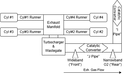
#### Narrowband O2 Sensor
An [oxygen sensor](https://en.wikipedia.org/wiki/Oxygen_sensor) (or O2 sensor) is a physical sensor that is incorporated into the exhaust piping of the engine, with one being placed immediately after the primary [catalytic converter](https://en.wikipedia.org/wiki/Catalytic_converter) in the Subaru DI factory arrangement.
Oxygen sensors, by interacting with exhaust gases, provide a value relative to the [stoichiometric](https://en.wikipedia.org/wiki/Stoichiometry) ratio that assists the ECU in approximating if the air-fuel ratio was richer (more fuel) or leaner (less fuel) than the ideal combustion ratio. It is important to underscore that these sensors are in essence providing an approximation of the relative direction of error of [lambda](https://en.wikipedia.org/wiki/Air%E2%80%93fuel_ratio#Air%E2%80%93fuel_equivalence_ratio_(%CE%BB)) value 1.0 of combustion. For example, a lambda value of 1.0 would be equal to an air-fuel ratio of about 14.7:1 for gasoline, and about 9.76:1 for E85. However, narrowband sensors cannot provide an accurate value for the combustion air-fuel ratio, only its relation to the stoichiometric ratio: if combustion was above or below that ratio, and a loose approximation of how significant the error is.
The role of the narrowband O2 sensor in the Subaru DI arrangement, being so limited in its capabilities, is not to determine the air-fuel ratio of combustion across a wide range of possible values. Instead, it is primarily used for managing the catalyst efficiency through trims and monitoring its effectiveness when the engine is commanding an air-fuel ratio close to a stoichiometric target.
Wideband Lambda Sensor (Closed Loop)
A wideband sensor is a physical sensor that is incorporated into the exhaust piping of the engine, with one being placed immediately before the primary catalytic converter in the Subaru DI factory arrangement.
Wideband sensors, by interacting with exhaust gases, provide to the ECU a close approximation of the air-fuel ratio ([lambda](https://en.wikipedia.org/wiki/Air%E2%80%93fuel_ratio#Air%E2%80%93fuel_equivalence_ratio_(%CE%BB))) condition that was present in the cylinder prior to combustion. This is a critically important sensor for Closed Loop control, as it provides the feedback value necessary to approximate the error between the commanded air-fuel target ratio and the physical combustion's indicated air-fuel ratio. The wideband sensor is able to sense this ratio as the exhaust gasses pass over it, flowing out of the engine through the exhaust piping where the wideband sensor is located after being collected by the [exhaust manifold](https://en.wikipedia.org/wiki/Exhaust_manifold).
Using the wideband sensor in Closed Loop mode, the ECU is able to calculate an overall air-fuel ratio (lambda) error and generally speaking modulates (trims) the injector pulse width accordingly to compensate for any inaccuracies (too rich or too lean) in its pulse width calculations.
### Subaru DI
#### Correction (Short-Term) Trims
**A/F Correction #1**
This is the short-term correction of the injector pulse width, sourced directly from the wideband lambda sensor. To produce this trim, the ECU first determines the error (delta) for the sensed air-fuel ratio (lambda) as it relates to the commanded air-fuel ratio. With this error, an excitation value is applied corresponding to the engine speed and load, effectively controlling the trim's activation based on the engine's operating condition.
This trim is only active in Closed Loop mode.
**A/F Correction #3**
This is the short-term correction of the air-fuel ratio (not to be confused with the injector pulse width), sourced directly from the narrowband O2 sensor. To produce this trim, the ECU determines a rough estimation of error from the narrowband O2 sensor.
This trim is only active in certain conditions, especially those that relate to the operation of the engine in an idle state, where the commanded air-fuel ratio is close to the stoichiometric ratio (or lambda 1.0).
#### Learning (Long-Term) Trims
**A/F Learning #1**
This is the long-term correction of the injector pulse width, sourced analytically from the wideband O2 sensor over time.
**A/F Learning #3**
This is the long-term correction of the air-fuel ratio (not to be confused with the injector pulse width), sourced analytically from the narrowband O2 sensor over time.
# Ignition Timing - Primary, Decel, and Startup
For more information on the basics of Ignition Timing and Detonation, see: [Ignition Timing and Knock Control](https://docs.motorsportsresearch.org/books/tuning/page/ignition-timing-knock-control).
### Targets
#### Acceleration (or "Primary")
##### Base and Dynamic Advance
This target is active when the accelerator pedal is depressed, or otherwise when conditions are met for the [](https://docs.motorsportsresearch.org/uploads/images/gallery/2025-02/wHX4oSnrXt7twvE9-parameter.png) **Ignition - Accel. Dynamics - Decel Active (⚑, ubyte)** parameter to be **zero**. Generally speaking, conditions where this target is active are wide open throttle ("WOT") and cruising (when the accelerator is pressed).
This ignition timing target and its associated tables and parameters are sorted under the **Ignition - Primary** folder and are comprised of four key **base** tables:
- **[](https://docs.motorsportsresearch.org/uploads/images/gallery/2025-02/9eh6kI73WySG3tND-table.png) Ignition - Primary - TGVs Closed (AVCS Disabled)**
- **[](https://docs.motorsportsresearch.org/uploads/images/gallery/2025-02/9eh6kI73WySG3tND-table.png) Ignition - Primary - TGVs Closed (AVCS Enabled)**
- **[](https://docs.motorsportsresearch.org/uploads/images/gallery/2025-02/9eh6kI73WySG3tND-table.png) Ignition - Primary - TGVs Open (AVCS Disabled)**
- **[](https://docs.motorsportsresearch.org/uploads/images/gallery/2025-02/9eh6kI73WySG3tND-table.png) Ignition - Primary - TGVs Open (AVCS Enabled)**
These four tables are first blended based on the corresponding blending values of [](https://docs.motorsportsresearch.org/uploads/images/gallery/2025-02/wHX4oSnrXt7twvE9-parameter.png) **Engine - AVCS Map Ratio (﹪, ubyte)** and t [](https://docs.motorsportsresearch.org/uploads/images/gallery/2025-02/wHX4oSnrXt7twvE9-parameter.png) **Engine - TGV Map Ratio (﹪, ubyte)**. The resulting base value can be monitored using the [](https://docs.motorsportsresearch.org/uploads/images/gallery/2025-02/wHX4oSnrXt7twvE9-parameter.png) **Ignition - Primary - Base Table (°, sbyte)** parameter.
Then, a **Dynamic Advance** value is calculated using the [](https://docs.motorsportsresearch.org/uploads/images/gallery/2025-02/wHX4oSnrXt7twvE9-parameter.png) **Knock Control - Dynamic Advance Multiplier (ubyte)**, commonly referred to as "*DAM*". This DAM value ranges from 0.00 to 1.00 and acts as a multiplier to the base dynamic advance table value. This base dynamic advance value is found by using the two primary base tables that are themselves blended using the TGV Map Ratio:
- **[](https://docs.motorsportsresearch.org/uploads/images/gallery/2025-02/9eh6kI73WySG3tND-table.png) Ignition - Primary - Advance - TGVs Closed (Base)**
- **[](https://docs.motorsportsresearch.org/uploads/images/gallery/2025-02/9eh6kI73WySG3tND-table.png) Ignition - Primary - Advance - TGVs Open (Base)**
The resulting blended, base value can be monitored using the [](https://docs.motorsportsresearch.org/uploads/images/gallery/2025-02/wHX4oSnrXt7twvE9-parameter.png) **Ignition - Primary - Advance - Table (°, ubyte)** parameter. This value is summed with the [](https://docs.motorsportsresearch.org/uploads/images/gallery/2025-02/wHX4oSnrXt7twvE9-parameter.png) **Ignition - Primary - Base Table (°, sbyte)** to produce a primary base target value.
##### Tuning Strategy
Tuning the Primary Ignition target maps is critical for any power-related objectives in the Subaru DI platforms, as these tables are designed to control the spark advance in all typical acceleration scenarios when throttle is applied.
With the tables under the **Ignition - Primary - Advance** controlled by the **Dynamic Advance Multiplier** (or DAM), this presents an opportunity to you as a tuner to determine how ignition advance should be delivered in scenarios where the DAM is lowered. The DAM is reduced by negative ignition events such as detonation, therefore these associated tables can be used to design areas of the ignition timing advance that, were detonation to be identified, timing may be removed.
#### Deceleration (or "Decel")
This target is active when the accelerator pedal is depressed, or otherwise when conditions are met for the [](https://docs.motorsportsresearch.org/uploads/images/gallery/2025-02/wHX4oSnrXt7twvE9-parameter.png) **Ignition - Accel. Dynamics - Decel Active (⚑, ubyte)** parameter to be **one**.
This ignition timing target and its associated tables and parameters are sorted under the **Ignition - Decel.** folder and are comprised of two key **base** tables:
- **[](https://docs.motorsportsresearch.org/uploads/images/gallery/2025-02/9eh6kI73WySG3tND-table.png) Ignition - Decel. - TGVs Closed**
- **[](https://docs.motorsportsresearch.org/uploads/images/gallery/2025-02/9eh6kI73WySG3tND-table.png) Ignition - Decel. - TGVs Open**